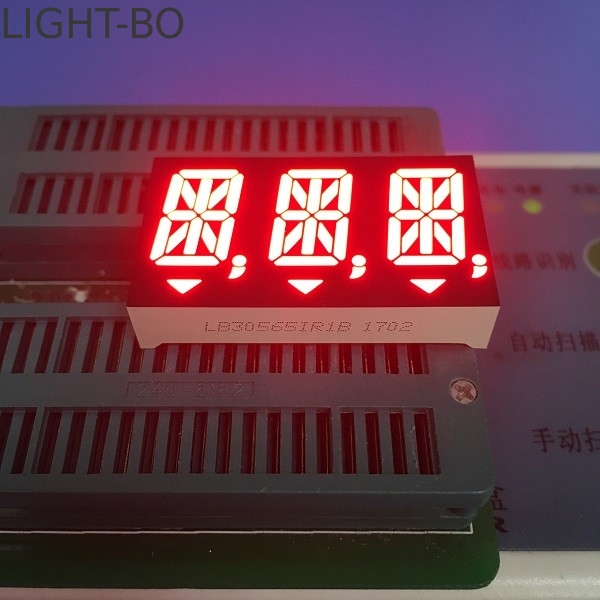
- 14 Segment Display Virtual
- 14 Segment Display Pinout Hex Code
- 14 Segment Display Printable
- 14 Segment Display Font
- 14 Segment Display Pinout
Then Built the project and make the connection between 7 Segment Display and 8051 Micro Controller as i showed in video. PDA54-11HWA, datasheet for PDA54-11HWA - 14 mm (0.54 inch) 14 segment dual digit alphanumeric display. Provided by Kingbright Corporation. PDA54-11HWA pdf documentation and PDA54-11HWA.
All Electronics has a fascinating multifunction LED display that includes seven 14-segment alphanumeric digits, four 7-segment numeric digits, and four LED icons. The Lite-On part number is LTM-Y2K19JF-03. It costs only $1 from All Electronics (CAT# DSY-1).
Design your own segment display with this Web App. Choose between 7, 14 or 16 segments, experiment with the settings for the geometry, colors and output formats. On the basis of your inputs, the App automatically generates the appropriate JavaScript source code. 0.30 inch small size blue 7 segment numeric led display 6 digits or 6 digit seven segment led display. Here are the 7-segment display markings sorted by sizes, this can often be seen on Ebay photos and reveal if they are specifying a wrong size.
Even if you’re not interested in the LTM-Y2K19JF-03, this article also describes removing epoxy, LED multiplexing, and a method for generating an alphanumeric font.
“Robot Room” displayed on a pair of alphanumeric LED modules. Also, I apparently I have email and voice mail messages waiting.
When purchased new from DigiKey, Liteon alphanumeric LEDs usually retail for $2 each (160-1108, LTP-587HR) or $3 (160-1011, LTP-3786E) for a multiplexed pair. So, $1 for 7 digits is a good deal even without considering the additional LEDs.
But what really caught my eye was the 5-pin hookup. Normally, numeric LEDs and alphanumeric LEDs have 8 to 18 pins that need to be connected to power, current-limiting resistors, a transistor (if multiplexed), and a display driver chip. A 5-pin connector for all of those LEDs indicates that the entire LED driving circuitry is built-in!
Left: The front of the Lite-On LTM-Y2K19JF-03 multifunction display showing the digits and icons. Right: The ST2225A-M LED driver chip and 5-pin connector.
Yes, in fact, the Lite-On LED display includes a built-in Silicon Touch Technology Inc (STTI) ST2225A, which is a 35-segment LED driver chip. The ST2225A controls current, so no LED resistors are needed. And, the Lite-On LED display also includes five Philips PMBT2907A PNP transistors (just visible through the protective epoxy), so they aren’t needed either.
Not only does the built-in circuitry reduce the expense and time of adding parts, but an external driver PCB isn’t necessary. This is a compact solution that is terrific for many small projects or tight spaces.
The ST2225A LED driver chip is controlled with two direct (non-addressed) signals: clock and data. In other words, it only uses two pins, doesn’t need I2C, and it doesn’t consume a microcontroller serial port. Because the clock speed is controlled by the transmitting device, it doesn’t need to be a particular frequency and is allowed to pause transmission at any time.
All of this means you can control the ST2225A with a lower-end microcontroller that lacks communication modules and where i/o pins may be at a premium. In fact, at the end of this article you'll see that I hooked up the LED display to an 8-pin microcontroller with only 2K of C code.
Downsides
What are the downsides and tradeoffs of this display module?

- It can’t be chopped down into smaller LED displays. (For example, you can’t cut out the 4-digit display.)
- The display is only available with a red output.
- LEDs use much more current (average of 200 mA @ 5V in this case) than LCDs. But, LEDs are brighter and look nicer.
- The part appears to be discontinued -- so get them while supplies last.
- All Electronics doesn’t provide pin-out information and I couldn’t locate the Lite-On datasheet on the web.
Fortunately, the rest of this article can help somewhat with that last bullet point.
Reverse Engineering an LED Display
The LTM-Y2K19JF-03 has a five pin, dual row, 0.1-inch-spaced connector. (3 by 3 with a middle pin missing on one row.) The entire module is encased in epoxy resin that prevents direct viewing of the circuitry. Therefore, without a Lite-On datasheet, the connector pins had to be determined through black-box analysis.
Update: After I posted this article, Marty Beem was kind enough to track down the datasheet and forward it to me. It confirms the information that was discovered experimentally.
Two of the pins are going to be power and ground. Scanning the ST2225A datasheet suggests a number of possibilities for the other pins. It also tells me that the lowest voltage for the chip is 4.5V - 5V. That’s what we'll use.
My first diagnostic technique with any unknown part connector is to compare each pin against the other with a multimeter in resistance mode. Then, the process is repeated with voltage measurement mode to see if any internal capacitors have been charged by the multimeter. Finally, the process is repeated with the multimeter in diode check mode (to see if I can find power polarity).
Usually, I learn enough from those steps to determine the power and ground pins. If I get those two pins right, then I figure I won’t blow the part when attempting to reverse-engineer the remaining pins with power supplied. Sadly, I learned squat.
It was time for a more dramatic approach.
Epoxy Removal
I researched epoxy removal on the Internet. Three techniques are generally prescribed:
- Heat the epoxy to soften it. This seems messy and it might damage the encased parts.
- Chemically remove the epoxy. The chemicals are a bit toxic and the plastic cases on the electronic components may also be affected.
- Scrape off the epoxy. This is probably the slowest approach and may damage the components unless I’m lucky and the epoxy cracks or flakes off.
Although I would have loved to remove all the epoxy to get a good look at the PCB and other components, the most important component that I need access to is the ST2225A. Luckily, the epoxy is thinnest over the ST2225A chip pins.
I examined the datasheet to determine the most critical pins for diagnostic purposes (power/Vdd, ground/Vss, clock, data, data enable, reset, and brightness). Then I decided to start scraping off the epoxy over those specific pins. Worst case, if the chip is damaged, the part only costs $1.
A reamer scrapes off epoxy from around an encapsulated chip.
I tried a razor blade, but it flexed too much. I switched to a reamer with a handle, which worked fairly well. (A reamer is a tool that is supposed to be for removing burrs from holes or slightly enlarging holes.)
Scraped epoxy becomes opaque. That makes it difficult to determine progress and to start being gentle when near the delicate pins. A dab of xylene applied with a Q-tip (cotton swab) dissolves the surface enough to restore clarity.
14 Segment Display Virtual
14 Segment Display Pinout Hex Code
Chip pins exposed after scratching off the surrounding epoxy.
At some point, the shine of freshly scratched metal became visible. Ahh, now the pinouts of the connector can be determined...
(Sorry this is a tad long, but I've marked the questions in bold!)
So I found these 14-segment alphanumeric LEDs online and wanted to control 16 of them using a TI microcontroller. Each alphanumeric LED has 15 pins, 1 for each segment and then one for the dot at the bottom right. If I wanted to power each one directly, I'd need 240 GPIO pins. Not ideal (and not possible).
My next idea was to control each individual LED square using two 8-bit SIPO shift registers. The thing is, I'd need 2 of these for every single LED square, meaning I'd have to use 32 in total. Again, not ideal.
My final idea was to use only two 8-bit SIPO shift registers, but 'redirect' the collective 16-bit output to an individual square using some sort of circuit. I know decoders are one-to-many, but they only send one bit out. I need a circuit that sends 16-bit data. I'm thinking this involves combining a ton of decoders, like this chip which has two 1-to-4 decoders in it. This seems really inefficient though. What sort of circuit would I need for this type of redirect?
Also, my problem is that each square will only be lit 1/16 of the time, so they'll be 1/16 as bright. I could pass 16 times the current, but that just sounds like a bad idea... How do I make sure the LEDs are operating at their brightest?
14 Segment Display Printable
Also, is there a way to have the LED's 'persist' using some sort of memory? If the values of the square don't change, then I don't see why I need to keep cycling through them. Would a gated D-latch do the trick?
14 Segment Display Font

14 Segment Display Pinout
Please let me know if I'm going about this all wrong. This is my first time trying something this complex, and I'm a bit lost at the moment.